thoughts on the function of music in our society

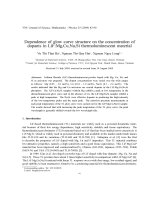
Báo cáo khoa học: The influence of heterodimer partner ultraspiracle/retinoid X receptor on the function of ecdysone receptor pot
- 12
- 398
- 0

PHYSICS AND POLITICS OR THOUGHTS ON THE APPLICATION OF THE PRINCIPLES OF ''''NATURAL SELECTION'''' AND ''''INHERITANCE'''' TO POLITICAL SOCIETY pptx
- 143
- 597
- 0

NOTES ON THE ROLE OF EDUCATION IN PRODUCTION FUNCTIONS AND GROWTH ACCOUNTING pot
- 59
- 595
- 0

A Modern Treatise on the Principle of Legality in Criminal Law doc
- 214
- 2.1K
- 0

The Protocol on the Rights of Women in Africa: An Instrument for Advancing Reproductive and Sexual Rights pot
- 25
- 409
- 0
Guidance for National Tuberculosis Programmes on the management of tuberculosis in children pptx
- 7
- 477
- 0

Báo cáo khoa học: Protein engineering of pyruvate carboxylase Investigation on the function of acetyl-CoA and the quaternary structure doc
- 10
- 397
- 0

An analysis on the effectiveness of conversion in daily conversations Focus on English - major students at Hai Phong Private University
- 51
- 729
- 0
A study on the images of objects in English idioms, proverbs and sayings
- 52
- 846
- 11

Update on the management of constipation in the elderly: new treatment options doc
- 9
- 850
- 0

Chapter 2Communicating Over the Network Quangkien@gmail.com.OverviewDescribe the structure of a network, including the devices and media that are necessary for successful communications. Explain the function of protocols in network communications. Ex potx
- 52
- 550
- 0
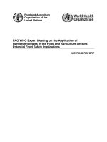
FAO WHO Expert Meeting on the Application of Nanotechnologies in the Food and Agriculture Sectors Potential Food Safety Implications
- 104
- 453
- 0

a systematic review of the research literature on the use of phonics in the teaching of reading and spelling
- 85
- 570
- 0
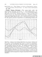
steinmetz cp discussion on 'the effect of iron in distorting alternating-current wave-form
- 20
- 439
- 0