lò vi sóng sharp r 21a1 s vn


Sử dụng lò vi sóng
Ngày tải lên :
17/09/2013, 20:10
... - 10:06 AM
Lò nấu vi s ng
Lò Vi s ng (Microwave oven - s ng cực ngắn) hiện nay đã ngự trị trong bếp của nhiều gia
đình cũng như tại công s , trường học…. Dân giầu có thì s m một lò gắn vào tường ... (pacemaker) vì các y cụ này đều được
che chở chống phóng xạ hoặc vi s ng.
â Copyright 2000-2003 Vinacomm, all rights reserved. S dng phiờn bn 2.0 ca phn mm iCMS
đ Ghi r nguồn "irv.moi.gov .vn& quot; ... nổ.
Lò vi ba cũng thường được dùng để hâm s a cho trẻ thơ. Vài điều
cần để ý là:
- S phân phối s c nóng trong lò vi ba không đồng đều, nên nhiều
khi bên ngoài bình s a thấy lạnh mà s a trong...
- 4
- 3.1K
- 20

Microstrip bộ lọc cho các ứng dụng lò vi sóng RF (P1)
Ngày tải lên :
24/10/2013, 16:15
... applications.
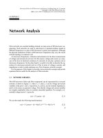
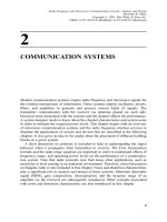
The study starts with a brief discussion of typical HTS subsystems and RF modules
that include HTS microstrip filters for cellular base stations. This is followed by
more detailed descriptions ... provide more accurate design with less design iterations, leading to
first-pass or tuneless filters. This chapter discusses computer simulation and/or
computer optimization. It summarizes some basic ... cascaded quadruplet (CQ) fil-
ters, trisection and cascaded trisection (CT) filters, cross-coupled filters using
transmission line inserted inverters, linear phase filters for group delay equaliza-
tion,...
- 5
- 649
- 1
Microstrip bộ lọc cho các ứng dụng lò vi sóng RF (P2)
Ngày tải lên :
24/10/2013, 16:15
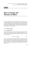
... variables are called scattering transmission or transfer parameters, de-
noted by T, and the matrix containing the all T parameters is referred to as scattering
transmission or transfer matrix.
If ... two or more simpler networks appears to be used
most frequently in analysis and design of filters. This is because most filters consist
of cascaded two-port components. For simplicity, consider ... analysis. For
a reciprocal network S
12
= S
21
. If the network is symmetrical, an additional property,
S
11
= S
22
, holds. Hence, the symmetrical network is also reciprocal. For a lossless
passive...
- 22
- 428
- 0
Microstrip bộ lọc cho các ứng dụng lò vi sóng RF (P3)
Ngày tải lên :
28/10/2013, 23:15
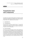
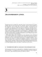
... plane where t is defined is called the t-
plane. Equation (3.51) is referred to as Richards’ transformation. For lossless pas-
sive networks p = j
and the Richards’ variable is simply expressed ... as the Gaussian lowpass
prototype filters, since the Gaussian filters are all-pole filters, as the Butterworth or
Chebyshev filters are. The element values of the Gaussian prototype filters are ... is increased. Therefore, filters de-
signed using immittance inverter theory are best applied to narrow-band filters.
3.5 RICHARDS’ TRANSFORMATION AND KURODA IDENTITIES
3.5.1 Richards’ Transformation
Distributed...
- 48
- 360
- 0
Microstrip bộ lọc cho các ứng dụng lò vi sóng RF (P4)
Ngày tải lên :
28/10/2013, 23:15
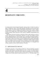
... discontinuities are still useful whenever they are appropriate. These
expressions are used in many circuit analysis programs. There are numerous closed-
form expressions for microstrip discontinuities available ... mi-
crostrip patch resonators is their lower conductor losses as compared with narrow
microstrip line resonators. Although patch resonators tend to have a stronger radia-
tion, they are normally ... literature, they are summarized here for easy reference.
4.1 MICROSTRIP LINES
4.1.1 Microstrip Structure
The general structure of a microstrip is illustrated in Figure 4.1. A conducting strip
(microstrip...
- 31
- 486
- 0

Microstrip bộ lọc cho các ứng dụng lò vi sóng RF (P5)
Ngày tải lên :
07/11/2013, 21:15
... capacitance C
6
shorts out transmission
by having infinite shunt susceptance.
A microstrip filter structure that can realize, approximately, such a filtering char-
acteristic is illustrated in Figure 5.6(b), ... However, if the removal of all lumped capacitors is desired for
stripline realization, a staggered stripline resonator array may be used to restore a
5.2 BANDPASS FILTERS
149
FIGURE 5.23 (a) A ... 5.1.3 Semilumped Lowpass Filters Having Finite-Frequency
Attenuation Poles
The previous two types of microstrip lowpass filter realize the lowpass prototype
filters having their frequencies of...
- 51
- 670
- 1

Microstrip bộ lọc cho các ứng dụng lò vi sóng RF (P6)
Ngày tải lên :
07/11/2013, 21:15
... Chebyshev lowpass prototype with a passband ripple of 0.1 dB
is chosen for design a microstrip bandstop filter, as shown in Figure 6.8. The mi-
crostrip bandstop filter uses L-shaped resonators coupled ... short-circuited,
quarter-wavelength resonators having one end short-circuited.
A simple and general approach for design of narrow-band bandstop filters is
based on reactance/susceptance slope parameters of the resonators. ... parameters. A practical and general tech-
nique that allows one to extract slope parameters of microwave bandstop resonators
using EM simulations or experiments is discussed next.
Consider a two-port...
- 30
- 444
- 0

Microstrip bộ lọc cho các ứng dụng lò vi sóng RF (P7)
Ngày tải lên :
07/11/2013, 21:15
... lowpass
or bandstop filters because of their frequency characteristics. However, these PBG
structures can be integrated with many microstrip filters discussed in the previous
chapters to improve ... structures.
Before we discuss ferroelectric tunable filters, some properties of ferroelectric ma-
terials will be described first.
7.2.1 Ferroelectric Materials
A ferroelectric material exhibits spontaneous ... films [18–44]. For the design
of HTS microstrip filters, it is essential to understand some important properties of
superconductors and substrates for growing HTS films. These will be described...
- 44
- 636
- 0
Tài liệu Microstrip bộ lọc cho các ứng dụng lò vi sóng RF (P8) doc
Ngày tải lên :
15/12/2013, 06:15
... load or port to form a two-port network, as
Figure 8.13 shows, where T–TЈ represents the symmetrical plane and the single LC
resonator has been separated into two symmetrical parts. When the symmetrical
plane ... two resultant coupling coefficients
should have different signs.
Another two pairs of coupled microstrip resonators are considered next , they are
the mixed coupling structures shown in Figure ... g
2
for the synchronous tuning, and d =
0 for a zero offset.
Shown in Figure 8.16 are typical simulated resonant frequency responses of the
coupled resonator structures in Figure 8.15(a) and (b), respectively,...
- 38
- 555
- 2
Tài liệu Microstrip bộ lọc cho các ứng dụng lò vi sóng RF (P9) doc
Ngày tải lên :
15/12/2013, 06:15
... these cells. Larger cells yields faster simulations, but at the expense of
larger errors. Errors are diminished by using smaller cells, but at the cost of longer
simulation times. It is important ... more accurate design
with less design iterations, leading to first-pass or tuneless filters. This not only re-
duces the labor intensiveness and so the cost, but also shortens the time from design
to ... a
filter, which are realized using microstrip or other microwave transmission line
structures.
Usually, there are various constraints on the designable parameters for a feasible
solution obtained...
- 42
- 695
- 3
Tài liệu Microstrip bộ lọc cho các ứng dụng lò vi sóng RF (P10) pptx
Ngày tải lên :
15/12/2013, 06:15
... results are plotted in Figure 10.17.
10.4 ADVANCED FILTERS WITH TRANSMISSION LINE INSERTED
INVERTERS
10.41 Characteristics of Transmission Line Inserted Inverters
An ideal immittance inverter ... linear phase filters.
10.6.1 Extracted Pole Synthesis Procedure
Since most transfer functions may be realized by lowpass prototype filters with a
symmetrical cross-coupled double array network, ... four filters show asymmetric frequency responses with one or two finite fre-
quency attenuation poles on the either side of the passband. This is because the
transmission line inserted inverters...
- 63
- 533
- 1
Tài liệu Microstrip bộ lọc cho các ứng dụng lò vi sóng RF (P11) ppt
Ngày tải lên :
15/12/2013, 06:15
... bandpass fil-
ters.
Figure 11.29 shows the structure of an aperture-coupled, microstrip, open-loop
resonator bandpass filter, which consists of two arrays of microstrip open-loop
resonators that are ... can then represent the resonator.
To demonstrate the characteristics of this type of slow-wave resonator, a single
resonator was first designed and fabricated on a RT/Duroid substrate having a
thickness ... size compared with other filters
such as waveguide filters. Nevertheless, for some applications where the size reduc-
tion is of primary importance, smaller microstrip filters are desirable, even...
- 53
- 458
- 2
Tài liệu Microstrip bộ lọc cho các ứng dụng lò vi sóng RF (P12) pptx
Ngày tải lên :
15/12/2013, 06:15
... fabrication errors. Among several possible error sources we have
identified that the thickness of the substrates used is a main source. The tolerance of
substrate thickness is ±5%. This tolerance ... factor against the
substrate thickness. (b) Simulated relative frequency shift of microstrip, meander, open-loop resonators
against the substrate thickness.
three loss mechanisms should usually ...
Microstrip
Circuit
LNA
FIGURE 12.2 RF module with dual-sided six channels of HTS microstrip filters and LNAs.
12.3 PRESELECT HTS MICROSTRIP BANDPASS FILTERS
12.3.1 Design Considerations
As has been described early...
- 25
- 372
- 0

Tài liệu RF và mạch lạc lò vi sóng P1 ppt
Ngày tải lên :
15/12/2013, 11:15
... Microwave Solid-State Devices
Devices Applications Advantages
Transistors L-band transmitters for telemetry
systems and phased-array radar
systems; transmitters for
communication systems
Low cost, ... high-power microwave
devices because these are easy to manufacture in comparison with circular
waveguides. However, certain devices (such as rotary joints) require a circular
cross-section. The ridged ... solid-state devices are listed in Table 1.4.
Figure 1.5 lists some applications of microwaves. Besides terrestrial and satellite
communications, microwaves are used in radar systems as well as in...
- 8
- 1.1K
- 10
Tài liệu RF và mạch lạc lò vi sóng P2 pdf
Ngày tải lên :
15/12/2013, 11:15
... 2:5:31
For simplicity, we assume that the k
i
are real and the đrst three terms of this series are
sufđcient to represent its output signal. Further, it is assumed that the input signal
has two different ... that intercepts an
incident power density w
inc
and gives an isotropically scattered power of 4pr
2
w
r
for
a back-scattered power density. Radar cross-sections of selected objects are listed
in ... Transmission Formula and the Radar Range Equation
Analysis and design of communication and monitoring systems often require an
estimation of transmitted and received powers. Friis transmission formula...
- 48
- 748
- 4
Tìm thêm:
- hệ việt nam nhật bản và sức hấp dẫn của tiếng nhật tại việt nam
- xác định các mục tiêu của chương trình
- xác định các nguyên tắc biên soạn
- khảo sát các chuẩn giảng dạy tiếng nhật từ góc độ lí thuyết và thực tiễn
- khảo sát chương trình đào tạo của các đơn vị đào tạo tại nhật bản
- khảo sát chương trình đào tạo gắn với các giáo trình cụ thể
- xác định thời lượng học về mặt lí thuyết và thực tế
- tiến hành xây dựng chương trình đào tạo dành cho đối tượng không chuyên ngữ tại việt nam
- điều tra đối với đối tượng giảng viên và đối tượng quản lí
- điều tra với đối tượng sinh viên học tiếng nhật không chuyên ngữ1
- khảo sát thực tế giảng dạy tiếng nhật không chuyên ngữ tại việt nam
- khảo sát các chương trình đào tạo theo những bộ giáo trình tiêu biểu
- nội dung cụ thể cho từng kĩ năng ở từng cấp độ
- xác định mức độ đáp ứng về văn hoá và chuyên môn trong ct
- phát huy những thành tựu công nghệ mới nhất được áp dụng vào công tác dạy và học ngoại ngữ
- mở máy động cơ lồng sóc
- mở máy động cơ rôto dây quấn
- các đặc tính của động cơ điện không đồng bộ
- hệ số công suất cosp fi p2
- đặc tuyến hiệu suất h fi p2