installation of pressurized apparatus and other uses of the pressurization technique bs 5345 part 5 1983 bs en 50016 1995 bs en 60079 14 1997

mcmillan, a. (1998). electrical installations in hazardous areas
Ngày tải lên :
18/04/2014, 11:03
... of pressurized apparatus and other uses of the pressurization technique 50 4 50 5 50 6 50 6 50 7 50 7 50 9 51 0 51 4 51 6 52 0 52 0 52 8 53 3 53 3 53 3 53 4 53 8 19.1 Standards for pressurization 53 9 19.2 Certification/approval ... Multiple enclosures 19.8 Typical pressurization control system 53 9 54 0 54 1 54 4 54 6 54 8 55 0 55 1 55 1 55 2 55 3 55 4 55 4 55 4 55 6 55 7 Contents xv 19.9 Pressurized enclosures in dust risks 19.10 Analyser houses ... and Zone 20 intrinsically safe circuits 20 .5. 6 Special circuits 56 7 56 8 56 9 56 9 57 0 57 1 57 2 21 Documentation, inspection, test and maintenance of 57 2 57 3 57 3 57 4 57 7 58 1 58 4 58 7 58 7 58 9 59 1 59 5...
- 678
- 961
- 0

iec 60092-375 ship board telecommunication cables and radio-frequency cables - general instrumentation, control and communication cables
Ngày tải lên :
25/12/2013, 10:44
... if the reference number consists of two numerals, these are disposed one below the other and the dash is placed underneath the lower numeral Spacing and dimensions of the marks The dimensions of ... polyethylene compound R 85 and of plain copper with polyvinyl chloride compound V 75 or silicone rubber compound S 95 A separation tape between the conductors and the insulation, when the latter is of ... separator between the screening braid and the sheath, when the latter is of polychloroprene or chlorosulphonated polyethylene, may be applied SECTION TWO - REQUIREMENTS 11 Conductor The conductors...
- 28
- 400
- 3

dye, n. (2000). radio frequency transistors - principles and practical applicat
Ngày tải lên :
18/04/2014, 12:26
... the high and low end of the frequency band of the amplifier Flatness, on the other hand, is defined as the deviation (at any frequency in the band) from an ideal gain, which is determined theoretically ... f,3 to provide the desired gain at the frequency of operation If the application is switching, then the higher the cutoff frequency, generally the faster the switching capability of the device A ... modulation Then, one channel frequency is removed and the presence of a signal at the frequency of the removed channel is measured The signals existing in the “off” channel are a result of triple...
- 317
- 504
- 1

Advanced Radio Frequency Identification Design and Applications Part 1 ppt
Ngày tải lên :
19/06/2014, 23:20
... development and enhancement Since most RFID tags comprise of an antenna and chip (ASIC), the design of both are presented in the first section of the book The initial chapter presents the basic the theoretical ... the receiving antenna shown in Fig is a tag antenna, then the load presented to the tag antenna is a chip In fact, the transmission line between the tag antenna and the chip is very short, hence ... applications of RFID The book is divided into two sections The first section of the book presents the theory and design of RFID tags – physical layer The second section of the book focuses on novel...
- 20
- 409
- 0

Advanced Radio Frequency Identification Design and Applications Part 2 potx
Ngày tải lên :
19/06/2014, 23:20
... phenomenon is easily understood since the metal beside will degrade the performance of the tag antenna Then, the tag antenna, the aluminum plate behind the tag antenna and the reader antenna 25 ... definitely dependent on the computing ability of the equipment used The influences of the environment on the antenna gains and input impedance can be obtained directly, hence people may argue that the Friis ... reality the characteristic impedance of the transmission line between the reader antenna and the reader is 50 Ω As for the characteristic impedance of the transmission line between the tag antenna and...
- 20
- 423
- 0

Advanced Radio Frequency Identification Design and Applications Part 3 pptx
Ngày tải lên :
19/06/2014, 23:20
... - 15. 12 35. 35+ j3 1.39 6.12 50 91.8X40.7 - 15. 34 36.61+j6.4 1 .14 5. 95 55 90.4X 45. 3 -14. 84 35. 21+j4 .5 1 .149 5. 95 60 88 X 48.6 -12.6 32 .55 +j8 .5 1.27 5. 97 70 81.2X52 .5 -11.8 29.83+j3.8 0.86 5. 66 80 ... apex angle of 45 (S3- 45 ), as shown in Fig 14, while the other is the standard Sierpinski dipole of apex angle 60° (S3-60°) Fig 14 The modified Seirpinski dipole antenna (S3- 45 ) The effective ... -12 .5 32.9+j9 .5 0.88 5. 72 K3 91. 25 X 14 -11 .56 29.1-j1.4 0.72 5. 55 Table Effect of indentation angle on Koch fractal dipole parameters Another indentation angle search between 20° and 30° is carried...
- 20
- 523
- 0

Advanced Radio Frequency Identification Design and Applications Part 4 pot
Ngày tải lên :
19/06/2014, 23:20
... the real part of the input impedance Figures 12(a) and 12(b) present the real and imaginary part of the input impedance as a function of the length of the stub l, respectively The imaginary part ... were taken at 2.45GHz, which is the central frequency of the free 2.4GHz part of the spectrum Figure 15, 16 and 17 show the comparison between simulated and measured results and good agreement can ... dipole Figures 7(a) and 7(b) present the real and imaginary part of the input impedance as a function of W1, respectively Figures 8(a) and 8(b) present the real and imaginary part of the input impedance...
- 20
- 499
- 0

Advanced Radio Frequency Identification Design and Applications Part 5 pptx
Ngày tải lên :
19/06/2014, 23:20
... diameter of the antenna wire is denoted by d A comprehensive treatment of this antenna has been given by Kraus [8] In Kraus’s study, the antenna current was divided across the straight part and circular ... helical antenna 3.1 Features of NMHA The structural parameters of the NMHA are shown in Fig 3.1 The length, diameter, and number of turns of the antenna are denoted by H, D, and N, respectively The ... view of antenna wire Figure 3.11 shows a cross-sectional view of the antenna wire The parameters W, t, and L represent the width, thickness, and total length of the wire, respectively, and δ is the...
- 20
- 599
- 0

Advanced Radio Frequency Identification Design and Applications Part 6 potx
Ngày tải lên :
19/06/2014, 23:20
... Antenna for Metal-Proximity Applications the presence and absence of the tap feed When the tap feed is used, the antenna impedance is exactly 50 Ω, and this confirms the effectiveness of the ... Figs 5. 6(a) and (b) The tap structure is rather simple Wire diameters of 0.8 mm and 0 .5 mm are selected for the antenna and the tap, respectively Because the spacing between the antenna and the ... that the antenna can be used in an RFID tag The simulation configuration is shown in Fig 5. 1 The antenna thickness is T, and the size of the metal plate is M The spacing between the antenna and the...
- 20
- 357
- 0

Advanced Radio Frequency Identification Design and Applications Part 7 pdf
Ngày tải lên :
19/06/2014, 23:20
... wavelength of the transmitting frequency by the reader, R is the distance between the antenna on the reader and the antenna on the tag and q is the impedance mismatch factor (0 ≤ q ≤ 1) between the ... into the tap arm The antenna and IC are placed on a piece of polystyrene foam attached to the metal plate The thickness of the foam is 1 .5 mm, and the size of the square metal plate is 0 .5 5. 4 ... and the antenna Equation (1) assumes a polarization match between the antenna used by the reader and the antenna on the passive tag Therefore, a good match between the passive IC and the antenna...
- 20
- 465
- 0

Advanced Radio Frequency Identification Design and Applications Part 9 pot
Ngày tải lên :
19/06/2014, 23:20
... to the design and development of the chipless RFID tag a comprehensive literature review of RFID tags was conducted The goal of the literature review was to identify the niche areas of design and ... outside the operating band of the chipless RFID tag, hence resulting in the absence of the resonance This is characterized as a logic “1” bit in the spectral signature The removal of the shorting ... larger percentage of tags were damaged when the ground plane was present than when not However, the ground plane seemed to alter results when testing other factors Therefore, the remainder of the results...
- 20
- 492
- 0
Advanced Radio Frequency Identification Design and Applications Part 10 pdf
Ngày tải lên :
19/06/2014, 23:20
... tracking If an adversary constantly observes the replies of a particular tag, she can track the movements of this tag and also the movements of a tag holder Another security problem is tag cloning ... which have been proposed in this area in Section In Section 4, we point out the vulnerabilities of the previous works, and then analyze the security and privacy requirements of the RFID tag search ... idi λ ← −−−− − then send λ = h( f (r j , ti )||n t ) ⊕ idi n t else choose random number rand and n t λ ← −−−− − verify h( f (r j , ti )||n t ) ⊕ idi then send λ = rand n t with the predefined...
- 20
- 376
- 0

Advanced Radio Frequency Identification Design and Applications Part 11 docx
Ngày tải lên :
19/06/2014, 23:20
... 2.7E-0 05 (16,19, 25) ( 15, 20, 25) ( 15, 19, 25) ( 15, 18, 25) 5. 590 5. 634 5. 650 5. 674 0.0009 0.00 05 0.0011 0.0012 Table The experimental results after the random sampling post process of the acquired data The ... velocities of the mobile robot(Borenstein and Feng, 1996) The systems integrate these informations to estimate the current position and the heading angle The cost of the INS systems was very high and the ... The simulation setting is the same as Section 4.1 In addition, we calculate the center of mass and the variances of the sample point of each partitions The results are represented in Fig 14 and...
- 20
- 358
- 0
Advanced Radio Frequency Identification Design and Applications Part 12 ppt
Ngày tải lên :
19/06/2014, 23:20
... 2008) The Q-value depends on the inductance and resistance of the tag’s pick-up coil These values will be distorted in the presence of the munition If the Qvalue for the tag is too low, the tag ... signal to the tag and (2) receiving a signal from the tag These two cases are independent because the amplitude of the signal received by the munition-mounted tag and the amplitude of the field ... navigates over the floor covered with tags, the antenna reads the positional information from the tag within the sensing region, which is then sent to the reader through the coaxial cable The reader...
- 20
- 371
- 0

Advanced Radio Frequency Identification Design and Applications Part 13 docx
Ngày tải lên :
19/06/2014, 23:20
... diameter ends There are other factors that can alter the field on the surface of the munition For example, the presence of other permeable or conductive material, such as the remnants of exploded ... expected, the presence of the munition decreased the inductance and increased the resistance of the tag’s circuit, thereby lowering the Q-value Figure 11 shows the induced eddy currents that change the ... positions of the tagged surrogates, and the diamonds indicate the position of the center of the transmit coil when data sets were recorded The depth of each tagged surrogate is indicated with text The...
- 20
- 414
- 0
Advanced Radio Frequency Identification Design and Applications Part 14 ppt
Ngày tải lên :
19/06/2014, 23:20
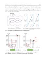
... of CM is valuable Number of transmitted bits 600000 50 0000 BS- CM (0.125q) 400000 BS- CM (0.25q) 300000 BS- CM (0.5q) 200000 BS- CM (q) BS 100000 250 50 0 1000 2000 4000 Number of tags Fig The identification ... solution depends on the number of tags, i.e q, and the position of these tags, i.e which leaf nodes they are located Moreover, the impact weight of the number of tags is more important than the other ... 0.25q For the aspect of the identification delay (Fig 5) , BS- CM (0.5q) shows the best performance as the total interrogation cycles for identifying all tags is reduced between 15. 5% (q= 250 ) and 17.7%...
- 20
- 393
- 0

Advanced Radio Frequency Identification Design and Applications Part 15 pdf
Ngày tải lên :
19/06/2014, 23:20
... or 80kHz) is generated after the assignment, then it begins to process the data right shift, encoding and CRC generation and checking CRC -5 and CRC-16 checking The main purpose of the Cyclic Redundancy ... fulfill it When the assignments of writing the FIFO in all tags are finished, a signal is given to the FGPA, and when the FPGA gets the signal, it begins to assign the data for the FIFO Each ... the discord between the I Q branches, but needs a high quality AD converter The DSP and FPGA chips are the cores of the baseband board, and this kind of system scheme is more and more prevalent...
- 14
- 419
- 0

Radio Frequency Identification Fundamentals and Applications, Bringing Research to Practice Part 1 potx
Ngày tải lên :
21/06/2014, 11:20
... 0.1 35 ≤ f < 0 .140 42 0 .140 ≤ f < 0 .14 85 37.7 0 .14 85 ≤ f < 30 -5 0.3 15 ≤ f < 0.600 -5 3. 155 ≤ f < 3.400 13 ,5 7.400 ≤ f < 8.800 9 10.20 ≤ f < 11.00 10 6.7 65 ≤ f < 6.7 95 13 .55 3 ≤ f < 13 .56 7 26. 957 ... Distance from the center on axis of symmetry of RWD antenna loop 100 z, m Fig Magnetic field strength for the transmitting antennas operating at the frequency of 1 25 kHz and 13 .56 MHz with a ... between the specified point of the RWD’s and the midpoint of the tag’s antenna loop It is very important because the magnetic field generated around the RWD’s antenna loop is not only medium of...
- 20
- 506
- 0

Radio Frequency Identification Fundamentals and Applications, Bringing Research to Practice Part 2 potx
Ngày tải lên :
21/06/2014, 11:20
... In FSA, when the number of tags is much larger than the number of slots, the identification delay increases considerably On the other hand, if the number of tags is low and the number of slots ... use the magnetic vector potential A when determining induction B in the tag placement area The dependences (40) and (42) show that there is continuity of vector potential at the boundary in the ... round the ferrite cores with a length of 0.1 25 m, diameter of 0.0 05 m and initial permeability of 20 Highlighted the discrepancy between simulation results and measurements was at the level of 3-4...
- 20
- 333
- 0
Radio Frequency Identification Fundamentals and Applications, Bringing Research to Practice Part 3 pdf
Ngày tải lên :
21/06/2014, 11:20
... the fundamental matrix, D, of the absorbing chain (Kemeny, 2009): D = ( I − F )−1 (4) As usual, I denotes the identity matrix, and F denotes the submatrix of P without absorbing states Then, c = ... row vector is denoted as V , the i-th component of a vector is denoted ( V )i, and σ( V ) denotes the sum of the values of the components of a vector V For the sake of simplicity, let us assume ... “orthogonal sequences”, and the other is called “pseudo random sequences” For instance, the well-known Walsh code is one of the orthogonal sequences and another well-known Gold code is one of widely...
- 20
- 367
- 0
- installation of the template
- determine the standard form of the equation of the line that passes through 0 5 and 4 0
- installation of the 3ds max exporter plugin
- g—local rules and procedures applicable to recovery of attorneys fees and other expenses under the equal access to justice act in ncua board adjudications
- during the installation of the mvfonts package the script prompts you for the destination d
- run the lpstat command to confirm installation of the printer
- installations in explosive atmospheres of gas vapour mist and dust bs 5345 part 1 1989 bs en 60079 14 1997 bs 6467 part 2 1988
- installation of intrinsically safe apparatus associated apparatus and intrinsically safe systems i bs 5345 part 4 1977 bsen 60079 14 1997
- genetics alternative therapies and other topics in the treatment of addiction
- differential diagnosis of amyloid in surgical pathology organized deposits and other materials in the differential diagnosis of amyloidosis
- disk spot test and other methods for the identification of anaerobes
- project trip report by b clarke on follow up training on installation of the rcfti computerized seed database and management and use of the database system 15 21st april 2007
- mitis and other streptococci are the main reservoir of genetic variability for s pnemoniae
- i groenning ba hildebrandt pr et al 2003 the influence of age sex and other variables on the plasma level of n terminal pro brain natriuretic peptide in a large sample of the general population heart 89 745 751
- 7 fabrication and installation of the rebar cage
Tìm thêm:
- hệ việt nam nhật bản và sức hấp dẫn của tiếng nhật tại việt nam
- xác định các mục tiêu của chương trình
- xác định các nguyên tắc biên soạn
- khảo sát các chuẩn giảng dạy tiếng nhật từ góc độ lí thuyết và thực tiễn
- khảo sát chương trình đào tạo của các đơn vị đào tạo tại nhật bản
- khảo sát chương trình đào tạo gắn với các giáo trình cụ thể
- xác định thời lượng học về mặt lí thuyết và thực tế
- tiến hành xây dựng chương trình đào tạo dành cho đối tượng không chuyên ngữ tại việt nam
- điều tra đối với đối tượng giảng viên và đối tượng quản lí
- điều tra với đối tượng sinh viên học tiếng nhật không chuyên ngữ1
- khảo sát thực tế giảng dạy tiếng nhật không chuyên ngữ tại việt nam
- khảo sát các chương trình đào tạo theo những bộ giáo trình tiêu biểu
- nội dung cụ thể cho từng kĩ năng ở từng cấp độ
- xác định mức độ đáp ứng về văn hoá và chuyên môn trong ct
- phát huy những thành tựu công nghệ mới nhất được áp dụng vào công tác dạy và học ngoại ngữ
- mở máy động cơ lồng sóc
- mở máy động cơ rôto dây quấn
- các đặc tính của động cơ điện không đồng bộ
- hệ số công suất cosp fi p2
- đặc tuyến hiệu suất h fi p2