McGraw Hill PIC Robotics A Beginners Guide to Robotics Projects Using the PIC Micro eBook-LiB Part 8 ppt

McGraw.Hill PIC Robotics A Beginners Guide to Robotics Projects Using the PIC Micro eBook-LiB Part 1 pdf
...
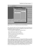
(EPIC) and a programming carrier board (hardware). The EPIC software
package has two executable files, one for DOS and another version of the soft-
ware for Windows.
It is the EPIC hardware and ... offers an enhanced and richer basic command
syntax than is available in the PicBasic compiler package. A few of the addition-
al commands that can be found in the Pro version al...

McGraw.Hill PIC Robotics A Beginners Guide to Robotics Projects Using the PIC Micro eBook-LiB Part 2 pot
... -p16f84 wink.bas
The compiler reads the text file and compiles two additional files, an .asm
(assembly language) and a .hex (hexadecimal) file.
The
wink.asm file is the assembly language equivalent ... simple. To install, run the
install.bat file on the 3.5-in EPIC diskette. The install.bat file exe-
cutes the main self-extracting program that automatically creates a s...

McGraw.Hill PIC Robotics A Beginners Guide to Robotics Projects Using the PIC Micro eBook-LiB Part 3 pps
... microcontroller installed onto the board. If you have an ac
adapter for the EPIC programmer board, plug it into the board. If not, attach
two fresh 9-V batteries. Connect the “battery on” jumper to apply ... disconnect the printer, if one is connected, and attach
the EPIC programming board, using a 6-ft DB25 cable.
When you connect the EPIC programming board to the...
McGraw.Hill PIC Robotics A Beginners Guide to Robotics Projects Using the PIC Micro eBook-LiB Part 4 ppt
...
the wink.bas program that is uploaded (programmed) into the 16F84 microcontroller.
I have noticed that when I place a brand new PICmicro 16F84 chip into the
EPIC compiler to program, EPIC always ... breadboard area.
gram, with the exception that we are only using one LED this time. The fol-
lowing are a small PicBasic program and PicBasic Pro program to blink an
LED on...
McGraw.Hill PIC Robotics A Beginners Guide to Robotics Projects Using the PIC Micro eBook-LiB Part 5 docx
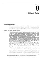
... rules to guide the robot in task performance.
Behavior-based programs create an “artificial” behavior in the robot that caus-
es it to reflectively (automatically) perform the task required. Behaviors ... allow the robot
to travel and move around the house in a random manner. The idea is that
while traveling in a haphazard manner, it will eventually make its way
thr...
McGraw.Hill PIC Robotics A Beginners Guide to Robotics Projects Using the PIC Micro eBook-LiB Part 6 pps
...
Building a Walter Tortoise
We can imitate most functions in Walter’s famous tortoise. My adaptation of
Walter’s tortoise is shown in Fig. 8. 1. To fabricate the chassis, we need to do a
little metalwork. ... Self-explanatory.
A well-stocked hardware store will carry the simple metalworking tools out-
lined. Most will also carry the light-gauge sheet metal and aluminum bar...

McGraw.Hill PIC Robotics A Beginners Guide to Robotics Projects Using the PIC Micro eBook-LiB Part 7 pps
... also vary from one another and then are not as closely matched.
Once you have a pair of CdS cells to use, they need to be attached to the
robot. I soldered the CdS cells and capacitors to a ... first look at how the standard program functions.
Fudge Factor
The variable RV (range value) is the fudge factor. At the beginning of the pro-
gram the variable RV is ass...

McGraw.Hill PIC Robotics A Beginners Guide to Robotics Projects Using the PIC Micro eBook-LiB Part 8 ppt
... vehicles.
The gearbox motor is a 918D type (see Fig. 9 .8) . The gearbox motor at the
top of the picture has an orange cowl that is covering the gears. Notice the flat
mounting bracket that is perfect ... 9.9).
The second gearbox motor is secured to the other side in a similar manner.
Back wheels
The shaft diameter of the gearbox motor is a little too small to...

McGraw.Hill PIC Robotics A Beginners Guide to Robotics Projects Using the PIC Micro eBook-LiB Part 9 pps
... memory the circuit uses an 8K
� 8 static RAM. There is a backup mem-
ory battery for the SRAM on the main board. This battery keeps the trained
words safely stored in the SRAM when the main power ...
Mounting the servomotors
The back servomotors are attached to the aluminum body using plastic 6-32
machine screws and nuts. The reason I used plastic screws is tha...

McGraw.Hill PIC Robotics A Beginners Guide to Robotics Projects Using the PIC Micro eBook-LiB Part 10 ppsx
... less than the interface board containing 10 relays. The advantage of the
relay board is that the miniature power relays have enough current capacity
to directly control small dc motors and other ... consideration was the type of output that the
interface board should provide. Here was a tough choice. I had the option to
make the output an active high signal that the...
Từ khóa:
- learning php data objects a beginners guide to php data objects pdf
- php this a beginners guide to learning object oriented php download
- a beginners guide to the study of religion pdf
- a beginners guide to the study of religion ebook
- a beginners guide to the study of religion herling
- php a beginners guide mcgraw hill professional
- php a beginners guide mcgraw hill
- beginners guide to embedded c programming using the pic microcontroller
- beginners guide to embedded c programming using the pic microcontroller pdf
- a practical guide to linux commands
- intellectual property and open source a practical guide to protecting code
- beginners guide to xhtml
- php a beginners guide
- a programmers guide to adonet in c
- beginners guide to ecommerce
- Báo cáo thực tập tại nhà thuốc tại Thành phố Hồ Chí Minh năm 2018
- Nghiên cứu sự biến đổi một số cytokin ở bệnh nhân xơ cứng bì hệ thống
- Một số giải pháp nâng cao chất lượng streaming thích ứng video trên nền giao thức HTTP
- đề thi thử THPTQG 2019 toán THPT chuyên thái bình lần 2 có lời giải
- NGHIÊN CỨU CÔNG NGHỆ KẾT NỐI VÔ TUYẾN CỰ LY XA, CÔNG SUẤT THẤP LPWAN SLIDE
- Quản lý hoạt động học tập của học sinh theo hướng phát triển kỹ năng học tập hợp tác tại các trường phổ thông dân tộc bán trú huyện ba chẽ, tỉnh quảng ninh
- Phát triển mạng lưới kinh doanh nước sạch tại công ty TNHH một thành viên kinh doanh nước sạch quảng ninh
- Phát triển du lịch bền vững trên cơ sở bảo vệ môi trường tự nhiên vịnh hạ long
- Nghiên cứu tổng hợp các oxit hỗn hợp kích thƣớc nanomet ce 0 75 zr0 25o2 , ce 0 5 zr0 5o2 và khảo sát hoạt tính quang xúc tác của chúng
- Nghiên cứu khả năng đo năng lượng điện bằng hệ thu thập dữ liệu 16 kênh DEWE 5000
- Định tội danh từ thực tiễn huyện Cần Giuộc, tỉnh Long An (Luận văn thạc sĩ)
- Thơ nôm tứ tuyệt trào phúng hồ xuân hương
- Sở hữu ruộng đất và kinh tế nông nghiệp châu ôn (lạng sơn) nửa đầu thế kỷ XIX
- Chuong 2 nhận dạng rui ro
- Tổ chức và hoạt động của Phòng Tư pháp từ thực tiễn tỉnh Phú Thọ (Luận văn thạc sĩ)
- Tăng trưởng tín dụng hộ sản xuất nông nghiệp tại Ngân hàng Nông nghiệp và Phát triển nông thôn Việt Nam chi nhánh tỉnh Bắc Giang (Luận văn thạc sĩ)
- Giáo án Sinh học 11 bài 15: Tiêu hóa ở động vật
- chuong 1 tong quan quan tri rui ro
- Nguyên tắc phân hóa trách nhiệm hình sự đối với người dưới 18 tuổi phạm tội trong pháp luật hình sự Việt Nam (Luận văn thạc sĩ)
- Giáo án Sinh học 11 bài 14: Thực hành phát hiện hô hấp ở thực vật