McGraw Hill PIC Robotics A Beginners Guide to Robotics Projects Using the PIC Micro eBook-LiB Part 4 ppt

McGraw.Hill PIC Robotics A Beginners Guide to Robotics Projects Using the PIC Micro eBook-LiB Part 1 pdf
... Left 242
Parts List 242
Chapter 14. Color Robotic Vision System 243
CMU Camera 244
Serial Communication 245
VB Application Program 248
Interfacing the CMU Camera to a Robot 250
PIC 16F 84 Runs ...
(EPIC) and a programming carrier board (hardware). The EPIC software
package has two executable files, one for DOS and another version of the soft-
ware for Windows.
It is t...

McGraw.Hill PIC Robotics A Beginners Guide to Robotics Projects Using the PIC Micro eBook-LiB Part 2 pot
... -p16f 84 wink.bas
The compiler reads the text file and compiles two additional files, an .asm
(assembly language) and a .hex (hexadecimal) file.
The
wink.asm file is the assembly language equivalent ... simple. To install, run the
install.bat file on the 3.5-in EPIC diskette. The install.bat file exe-
cutes the main self-extracting program that automatically creates a...

McGraw.Hill PIC Robotics A Beginners Guide to Robotics Projects Using the PIC Micro eBook-LiB Part 3 pps
... microcontroller installed onto the board. If you have an ac
adapter for the EPIC programmer board, plug it into the board. If not, attach
two fresh 9-V batteries. Connect the “battery on” jumper to apply ... disconnect the printer, if one is connected, and attach
the EPIC programming board, using a 6-ft DB25 cable.
When you connect the EPIC programming board to the...
McGraw.Hill PIC Robotics A Beginners Guide to Robotics Projects Using the PIC Micro eBook-LiB Part 4 ppt
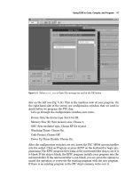
... command to communicate and output mes-
sages to the LCD display.
The PicBasic and PicBasic Pro compilers can send and receive serial
information at 300, 1200, 240 0, and 9600 Bd. Data are sent as ... breadboard.
4 (MCLR), a 4- MHz crystal with two (22-pF) capacitors and a 5-V power sup-
ply. Note: The 4- MHz crystal and two (22-pF) capacitors make up an oscillator
that is...
McGraw.Hill PIC Robotics A Beginners Guide to Robotics Projects Using the PIC Micro eBook-LiB Part 5 docx
... allow the robot
to travel and move around the house in a random manner. The idea is that
while traveling in a haphazard manner, it will eventually make its way
throughout the rooms,
cleaning the ... out-
put pins and then access them in our programs. There are other commands
you can use to accomplish the same thing.
The PicBasic and PicBasic Pro compilers have two ba...
McGraw.Hill PIC Robotics A Beginners Guide to Robotics Projects Using the PIC Micro eBook-LiB Part 6 pps
...
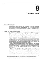
Building a Walter Tortoise
We can imitate most functions in Walter’s famous tortoise. My adaptation of
Walter’s tortoise is shown in Fig. 8.1. To fabricate the chassis, we need to do a
little metalwork. ... Remove the bearing from the output gear (see Fig. 8.10). The
bearing needs to be removed so that you can cut away the stop tab from the
gear. Use a hobby knif...

McGraw.Hill PIC Robotics A Beginners Guide to Robotics Projects Using the PIC Micro eBook-LiB Part 7 pps
... also vary from one another and then are not as closely matched.
Once you have a pair of CdS cells to use, they need to be attached to the
robot. I soldered the CdS cells and capacitors to a ... first look at how the standard program functions.
Fudge Factor
The variable RV (range value) is the fudge factor. At the beginning of the pro-
gram the variable RV is ass...

McGraw.Hill PIC Robotics A Beginners Guide to Robotics Projects Using the PIC Micro eBook-LiB Part 8 ppt
... 9.9).
The second gearbox motor is secured to the other side in a similar manner.
Back wheels
The shaft diameter of the gearbox motor is a little too small to make a good
friction fit to the ... on the front and
back legs. In the F position, the front and back legs are moved backward
simultaneously, causing the robot to move forward. The walking cycle can...

McGraw.Hill PIC Robotics A Beginners Guide to Robotics Projects Using the PIC Micro eBook-LiB Part 9 pps
... programming scenario, when the HM2007 recognizes a command, it can signal
an interrupt to the host CPU and then relay the command it recognized. The
HM2007 c
hip can be cascaded to provide a larger ... with the drilled holes.
4
Pressure is applied to bend the aluminum bar at a 90° angle. It’s best to apply
pressure at the base of the aluminum bar close to...

McGraw.Hill PIC Robotics A Beginners Guide to Robotics Projects Using the PIC Micro eBook-LiB Part 10 ppsx
... RB0/INT
VSS
VDD
U5
MCLR'
OSC1
OSC2
X1
4MHz
R11
4. 7KΩ
Vcc
Vcc
24
11
12
18
19
10
9
8
7
6
5
4
3
2
1
20
21
22
23
A
B
C
D
Q10
Q9
Q8
Q7
Q6
Q5
Q4
Q3
Q2
Q1
Q0
32
54
76
910
11 12
14 15
32
54
76
910
U 6a
40 49
U6b
40 49
U6c
40 49
U6d
40 49
U6e
40 49
U6f
40 49
U 7a
40 49
U7b
40 49
U7c
40 49
U7d
40 49
1
2
3
4
5
6
7
8
9
10
Output
741 54
Figure ... Input
U3
LM339
U 4a
4...
Từ khóa:
- chuyên đề điện xoay chiều theo dạng
- Nghiên cứu tổ chức pha chế, đánh giá chất lượng thuốc tiêm truyền trong điều kiện dã ngoại
- Nghiên cứu vật liệu biến hóa (metamaterials) hấp thụ sóng điện tử ở vùng tần số THz
- Nghiên cứu tổ chức chạy tàu hàng cố định theo thời gian trên đường sắt việt nam
- đề thi thử THPTQG 2019 toán THPT chuyên thái bình lần 2 có lời giải
- Biện pháp quản lý hoạt động dạy hát xoan trong trường trung học cơ sở huyện lâm thao, phú thọ
- Giáo án Sinh học 11 bài 13: Thực hành phát hiện diệp lục và carôtenôit
- Giáo án Sinh học 11 bài 13: Thực hành phát hiện diệp lục và carôtenôit
- ĐỒ ÁN NGHIÊN CỨU CÔNG NGHỆ KẾT NỐI VÔ TUYẾN CỰ LY XA, CÔNG SUẤT THẤP LPWAN
- Quản lý hoạt động học tập của học sinh theo hướng phát triển kỹ năng học tập hợp tác tại các trường phổ thông dân tộc bán trú huyện ba chẽ, tỉnh quảng ninh
- Phối hợp giữa phòng văn hóa và thông tin với phòng giáo dục và đào tạo trong việc tuyên truyền, giáo dục, vận động xây dựng nông thôn mới huyện thanh thủy, tỉnh phú thọ
- Trả hồ sơ điều tra bổ sung đối với các tội xâm phạm sở hữu có tính chất chiếm đoạt theo pháp luật Tố tụng hình sự Việt Nam từ thực tiễn thành phố Hồ Chí Minh (Luận văn thạc sĩ)
- Phát hiện xâm nhập dựa trên thuật toán k means
- Nghiên cứu, xây dựng phần mềm smartscan và ứng dụng trong bảo vệ mạng máy tính chuyên dùng
- Định tội danh từ thực tiễn huyện Cần Giuộc, tỉnh Long An (Luận văn thạc sĩ)
- Chuong 2 nhận dạng rui ro
- Giáo án Sinh học 11 bài 15: Tiêu hóa ở động vật
- chuong 1 tong quan quan tri rui ro
- Giáo án Sinh học 11 bài 14: Thực hành phát hiện hô hấp ở thực vật
- Giáo án Sinh học 11 bài 14: Thực hành phát hiện hô hấp ở thực vật