Where Am I-Sensors and methods for mobile robot positioning - Borenstein(2001) Part 13 pptx

Tài liệu Where am I? Sensors and Methods for Mobile Robot Positioning ppt
... iron and nickel) and mumetal (iron, nickel,
Where am I?
Sensors and Methods for
Mobile Robot Positioning
by
J. Borenstein , H. R. Everett , and L. Feng
123
Contributing authors: S. W. Lee and ... code
Part I
Sensors for
Mobile Robot Positioning
axis
n
co
n
cl
Waveguide
NA ' sin2
c
' n
2
co
&n
2
cl
2
1
Numerical aperture
Waveguide
axis
40 Part...

Where.Am.I-Sensors.and.methods.for.mobile.robot.positioning.-.Borenstein(2001) Part 2 ppsx
... Multi-Degree-of-Freedom Vehicles
Multi-degree-of-freedom (MDOF) vehicles have multiple
drive and steer motors. Different designs are possible. For
example, HERMIES-III, a sophisticated platform ... large
axis
n
co
n
cl
Waveguide
NA ' sin2
c
' n
2
co
&n
2
cl
2
1
Numerical aperture
Waveguide
axis
40 Part I Sensors for Mobile Robot Positioning
Figure 2.8: Step-index m...
Where.Am.I-Sensors.and.methods.for.mobile.robot.positioning.-.Borenstein(2001) Part 3 pps
... the same for both the
Andrew 3ARG-A and the Hitachi OFG-3 gyros: 0.05 /s. If either gyro was installed on a robot with
a systematic error (e.g., due to unequal wheel diameters; see Sec. 5.1 for ... while model 3ARG-D ($1,100) has
an RS-232 output for connection to a com-
puter. Technical specifications for the
3ARG-D are given in Table 2.1. Specifica-
tions for the 3ARG-A are si...

Where.Am.I-Sensors.and.methods.for.mobile.robot.positioning.-.Borenstein(2001) Part 5 pptx
... (Courtesy
of Massa Products Corp.)
Parameter E-220B/215 E-220B/150 E-220B/40 E-220B/26 Units
Range 10 - 61
4 - 24
20 - 152
8 - 60
61 - 610
24 - 240
61 - 914
24 - 360
cm
in
Beamwidth 10 10 35 (15) 35 (15)
Frequency ... 0.076
0.03
0.1
0.04
0.76
0.3
1
0.4
cm
in
Power 8 - 15 8 - 15 8 - 15 8 - 15 VDC
Weight 4 - 8 4 - 8 4 - 8 4 - 8 oz...

Where.Am.I-Sensors.and.methods.for.mobile.robot.positioning.-.Borenstein(2001) Part 6 pot
... 2
¾
5
2
cm
in
(velocity) 0.3 0.5 m/s
Beam divergence 2 2.8 mrad
Output (digital) RS-232, -4 22 RS-232, -4 22
(analog) 0-1 0 0-1 0 VDC
Power 1 1-1 8 1 1-1 8 VDC
10 10 W
Size 22 13 7.6
8.7×5.1×3
22 13 7.6
8.7×5.1×3
cm
in
Weight ... line
diode
Laser
Start
Stop
Peak
detector
Range
gate
Detector
Trigger
circuit
Threshold
detector
Ref
106 Part I Sensors for Mobile Robot Posit...

Where.Am.I-Sensors.and.methods.for.mobile.robot.positioning.-.Borenstein(2001) Part 7 doc
... compression circuit from in [Adams and Probert, 1995].
(Reproduced with permission from [Adams and Probert, 1995].)
138 Part II Systems and Methods for Mobile Robot Positioning
odometry with the ... diameters).
In the example here, this causes
a 3
o
orientation error.
Reference Wall
\designer\book\deadre30.ds4, deadre32.w mf, 07/19/95
134 Part II Systems and Methods...

Where.Am.I-Sensors.and.methods.for.mobile.robot.positioning.-.Borenstein(2001) Part 8 pptx
... zero, and the gyros should ideally show ).
Barshan and Durrant-Whyte determined that the standard deviation, here used as a measure for the
152 Part II Systems and Methods for Mobile Robot Positioning
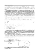
Triangulation
In ... [NAMCO,
1989]
= Vt - 45 (6.2)
b
where
= target angle
V = scan velocity (7,200 /s)
T = time between scan initiation and target
b
detection.
150...

Where.Am.I-Sensors.and.methods.for.mobile.robot.positioning.-.Borenstein(2001) Part 10 pot
... was said to be 15 centimeters (6 in).
182 Part II Systems and Methods for Mobile Robot Positioning
Figure 7.10: The odor-laying/odor-sensing mobile robot was
developed at Monash University in ...
The disadvantages of occupancy grid-based maps are that they:
194 Part II Systems and Methods for Mobile Robot Positioning
Figure 8.9: Siemens' Roamer robot is...

Where.Am.I-Sensors.and.methods.for.mobile.robot.positioning.-.Borenstein(2001) Part 11 pps
... δθ
θ
camera camera camera
sang03.cdr, .wmf
210 Part II Systems and Methods for Mobile Robot Positioning
Figure 9.3:
a. Possible camera locations (circular arc) determined by two rays and corresponding ... positioning means finding position and orientation of a sensor
or a robot. Since the general framework of landmark-based and map-based positioning, as well as the
met...
Từ khóa:
- tài liệu longman preparation series for the new toeic test part 36 pptx
- handbook of residue analytical methods for agrochemicals volume 1 and volume 2
- heating and cooling systems for mobile homes
- methods and materials for teaching the gifted pdf
- methods and materials for research paper
- methods and materials for teaching the gifted
- central heating and cooling systems for mobile homes
- mob subject 5 static and dynamic access methods for cellular networks
- heating and air conditioning units for mobile homes
- advanced mathematical methods for scientists and engineers pdf
- mathematical methods for scientists and engineers mcquarrie pdf
- mathematical methods for scientists and engineers pdf
- methods and materials for lab report
- advanced mathematical methods for scientists and engineers bender pdf
- advanced mathematical methods for scientists and engineers pdf download
- Báo cáo thực tập tại nhà thuốc tại Thành phố Hồ Chí Minh năm 2018
- Báo cáo quy trình mua hàng CT CP Công Nghệ NPV
- Nghiên cứu sự hình thành lớp bảo vệ và khả năng chống ăn mòn của thép bền thời tiết trong điều kiện khí hậu nhiệt đới việt nam
- Nghiên cứu vật liệu biến hóa (metamaterials) hấp thụ sóng điện tử ở vùng tần số THz
- Nghiên cứu tổ chức chạy tàu hàng cố định theo thời gian trên đường sắt việt nam
- đề thi thử THPTQG 2019 toán THPT chuyên thái bình lần 2 có lời giải
- Giáo án Sinh học 11 bài 13: Thực hành phát hiện diệp lục và carôtenôit
- ĐỒ ÁN NGHIÊN CỨU CÔNG NGHỆ KẾT NỐI VÔ TUYẾN CỰ LY XA, CÔNG SUẤT THẤP LPWAN
- Phát triển mạng lưới kinh doanh nước sạch tại công ty TNHH một thành viên kinh doanh nước sạch quảng ninh
- Nghiên cứu về mô hình thống kê học sâu và ứng dụng trong nhận dạng chữ viết tay hạn chế
- Nghiên cứu tổng hợp các oxit hỗn hợp kích thƣớc nanomet ce 0 75 zr0 25o2 , ce 0 5 zr0 5o2 và khảo sát hoạt tính quang xúc tác của chúng
- Thiết kế và chế tạo mô hình biến tần (inverter) cho máy điều hòa không khí
- Tổ chức và hoạt động của Phòng Tư pháp từ thực tiễn tỉnh Phú Thọ (Luận văn thạc sĩ)
- Kiểm sát việc giải quyết tố giác, tin báo về tội phạm và kiến nghị khởi tố theo pháp luật tố tụng hình sự Việt Nam từ thực tiễn tỉnh Bình Định (Luận văn thạc sĩ)
- Quản lý nợ xấu tại Agribank chi nhánh huyện Phù Yên, tỉnh Sơn La (Luận văn thạc sĩ)
- Tăng trưởng tín dụng hộ sản xuất nông nghiệp tại Ngân hàng Nông nghiệp và Phát triển nông thôn Việt Nam chi nhánh tỉnh Bắc Giang (Luận văn thạc sĩ)
- Tranh tụng tại phiên tòa hình sự sơ thẩm theo pháp luật tố tụng hình sự Việt Nam từ thực tiễn xét xử của các Tòa án quân sự Quân khu (Luận văn thạc sĩ)
- Giáo án Sinh học 11 bài 15: Tiêu hóa ở động vật
- chuong 1 tong quan quan tri rui ro
- Nguyên tắc phân hóa trách nhiệm hình sự đối với người dưới 18 tuổi phạm tội trong pháp luật hình sự Việt Nam (Luận văn thạc sĩ)