Camry Repair Manual BODY ELECTRICAL BODY

Camry Repair Manual BODY ELECTRICAL
... in-
spect the connector on the junction block side.
BE09Y–01
BODY ELECTRICAL BODY ELECTRICAL SYSTEM
BE–1
2221AuthorĂ: DateĂ:
BODY ELECTRICAL SYSTEM
PRECAUTION
Take care to observe the following ... Signal Light
BODY ELECTRICAL TURN SIGNAL AND HAZARD WARNING SYSTEM
BE–29
2249AuthorĂ: DateĂ:
TURN SIGNAL AND HAZARD WARNING SYSTEM
LOCATION
BE09Z–03
BE–2
BODY ELECTRICAL BODY...

Camry Repair Manual BODY ELECTRICAL BODY
... in-
spect the connector on the junction block side.
BE09Y–01
BODY ELECTRICAL BODY ELECTRICAL SYSTEM
BE–1
2221AuthorĂ: DateĂ:
BODY ELECTRICAL SYSTEM
PRECAUTION
Take care to observe the following ... Signal Light
BODY ELECTRICAL TURN SIGNAL AND HAZARD WARNING SYSTEM
BE–29
2249AuthorĂ: DateĂ:
TURN SIGNAL AND HAZARD WARNING SYSTEM
LOCATION
BE09Z–03
BE–2
BODY ELECTRICAL BODY...

Camry Repair Manual Body electrical
... or
bulb.
Switch position
OFF (Free)
ON (Lock)
Terminal
0)
c
o
N
t
o
(71
BODY ELECTRICAL SYSTEM Lighting
BE–19
BODY ELECTRICAL SYSTEM
BODY ELECTRICAL SYSTEM
BE–1
Taillight Failure Sensor
INSPECTION OF ... terminal 4 and the body ground, and 2 and the body
ground of the running light relay. Also, because the continuity is made between terminal 5 and the body
ground, and 3 and...
Camry Repair Manual Body
... possiblity that the body and/or parts may be
damaged, first remove the danger before performing repair
operations.
Example:
1. Apply protection tape to the body adjacent to the body part
when removing ... damaged while repairing other parts,
be sure to repair the anti–rust agent.
Example:
1. If body sealer, paint film or undercoat are damaged by
peeling, cracks, etc., be sure to...
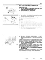
Camry Repair Manual AIR CONDITION
... sure to read the following item carefully, then
follow the correct procedure described in the repair manual.
AC21Y–01
I03338
Thermometer
Ice
10 cm
(0.39 in.)
Ohmmeter
Thermistor
Z04352
(Ω)
5,000
0
500
1,000
1,500
2,000
2,500
3,000
3,500
4,000
4,500
5010152025(°C)
32
41
50 ... CYLINDER
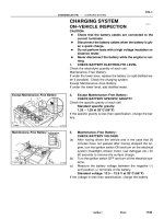
HINT:
When handling the charging cylinder, always follow the direc-
tions given in the instruction manua...
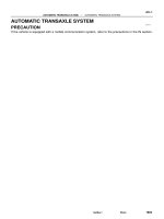
Camry Repair Manual AUTOMATIC TRANSAXLE
... TRANSAXLE (A140E) SHIFT SOLENOID VALVE SL
1903A uthorĂ: DateĂ:
SHIFT SOLENOID VALVE SL
ON–VEHICLE REPAIR
1. REMOVE PARK/NEUTRAL POSITION SWITCH
(See page AX–4)
2. DISCONNECT SHIFT SOLENOID VALVE ... TRANSAXLE (A140E) DIFFERENTIAL OIL SEAL
AX–11
1904A uthorĂ: DateĂ:
DIFFERENTIAL OIL SEAL
ON–VEHICLE REPAIR
1. REMOVE LH AND RH DRIVE SHAFTS
(See page SA–17)
2. REMOVE SIDE GEAR SHAFT OIL SEAL...
Camry Repair Manual AUTOMATIC TRANSAXLE MANUAL
... 16
Valve body x Transaxle case 10 100 7
Manual valve body x Transaxle case 10 100 7
Detent spring x Valve body 10 100 7
Oil tube bracket x Transaxle case 10 100 7
Oil strainer x Valve body 10 ... SPECIFICATIONS–
AX–18
TORQUE SPECIFICATION
Part tightened N·m kgf·cm ft·lbf
Stator shaft x Oil pump body 10 100 7
Upper valve body x Lower valve body 5.4 55 48 <in.lbf>
Ring gea...
Camry Repair Manual BRAKE
... Spring
No. 1 Piston and Spring
Cylinder Body
Stopper Bolt
S Gasket
Reservoir Set Screw
Grommet
Snap Ring
Grommet
Cap
Strainer
Reservoir
Reservoir Set Screw
Cylinder Body
S Gasket
Stopper Bolt
Grommet
Grommet
No. ... Push in the piston with a screwdriver, and remove the 2
straight pins by turning over the cylinder body.
HINT:
Tape the screwdriver tip before use.
(b) Remove the 2 pistons...
Camry Repair Manual CHARGING
... and turn on the electrical
system (headlight, blower motor, rear defogger etc.) for
60 seconds to remove the surface charge.
(b) Turn the ignition switch OFF and turn off the electrical sys-
tems.
(c) ... and turn on the electrical
system (headlight, blower motor, rear defogger etc.) for
60 seconds to remove the surface charge.
(b) Turn the ignition switch OFF and turn off the electric...
Camry Repair Manual CLUTCH
... continuity
CL036–01
Q10085
Filler Cap
Float
Reservoir
Tank
Slotted Spring Pin
zGrommet
Clutch Line
15 (155, 11)
Master Cylinder Body
zNon–reusable part
N·m (kgf·cm, ft·lbf)
: Specified torque
Spring
Piston
Push Rod
Snap Ring
Washer
Boot
Clip
12
Từ khóa:
- toyota camry repair manual 2000
- 2000 toyota camry repair manual download
- 2000 toyota camry repair manual free download
- 2000 toyota camry repair manual pdf
- 2000 toyota camry repair manual free
- 2000 toyota camry repair manual pdf download
- Báo cáo thực tập tại nhà thuốc tại Thành phố Hồ Chí Minh năm 2018
- Nghiên cứu sự biến đổi một số cytokin ở bệnh nhân xơ cứng bì hệ thống
- Nghiên cứu tổ chức pha chế, đánh giá chất lượng thuốc tiêm truyền trong điều kiện dã ngoại
- Nghiên cứu tổ hợp chất chỉ điểm sinh học vWF, VCAM 1, MCP 1, d dimer trong chẩn đoán và tiên lượng nhồi máu não cấp
- Một số giải pháp nâng cao chất lượng streaming thích ứng video trên nền giao thức HTTP
- Biện pháp quản lý hoạt động dạy hát xoan trong trường trung học cơ sở huyện lâm thao, phú thọ
- Giáo án Sinh học 11 bài 13: Thực hành phát hiện diệp lục và carôtenôit
- Giáo án Sinh học 11 bài 13: Thực hành phát hiện diệp lục và carôtenôit
- Giáo án Sinh học 11 bài 13: Thực hành phát hiện diệp lục và carôtenôit
- Giáo án Sinh học 11 bài 13: Thực hành phát hiện diệp lục và carôtenôit
- NGHIÊN CỨU CÔNG NGHỆ KẾT NỐI VÔ TUYẾN CỰ LY XA, CÔNG SUẤT THẤP LPWAN SLIDE
- Phối hợp giữa phòng văn hóa và thông tin với phòng giáo dục và đào tạo trong việc tuyên truyền, giáo dục, vận động xây dựng nông thôn mới huyện thanh thủy, tỉnh phú thọ
- Phát triển du lịch bền vững trên cơ sở bảo vệ môi trường tự nhiên vịnh hạ long
- Phát hiện xâm nhập dựa trên thuật toán k means
- Nghiên cứu, xây dựng phần mềm smartscan và ứng dụng trong bảo vệ mạng máy tính chuyên dùng
- Sở hữu ruộng đất và kinh tế nông nghiệp châu ôn (lạng sơn) nửa đầu thế kỷ XIX
- Chuong 2 nhận dạng rui ro
- Quản lý nợ xấu tại Agribank chi nhánh huyện Phù Yên, tỉnh Sơn La (Luận văn thạc sĩ)
- Tranh tụng tại phiên tòa hình sự sơ thẩm theo pháp luật tố tụng hình sự Việt Nam từ thực tiễn xét xử của các Tòa án quân sự Quân khu (Luận văn thạc sĩ)
- Giáo án Sinh học 11 bài 15: Tiêu hóa ở động vật